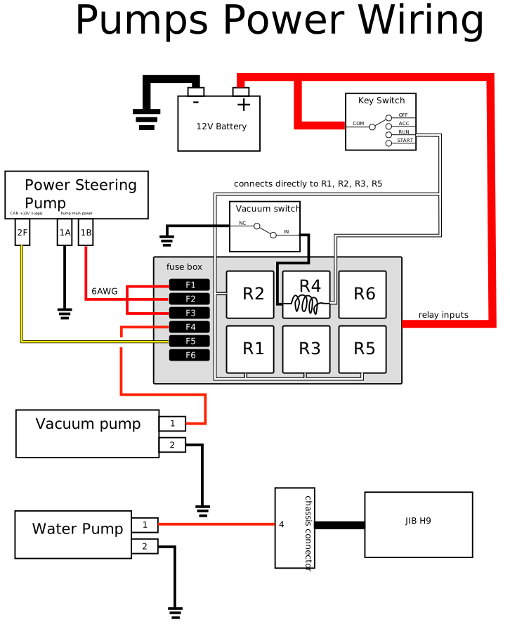
Schematics, Page 1: Pump Power
With the removal of the engine, I needed a way to provide power for the power-steering system, the brake booster, and the coolant pump because all of those were driven off of the crankshaft on the Subaru. Naturally, I wanted to find electrically-powered equivalents of all of these components.
Parts Selection
JIB-H9 VCU
This is a box that I purchased from a company called FlashDrive Motors that has a lot of nice little gewgaws in it that simplifies a lot of the low-voltage wiring for the conversion. I mention it here because it's ultimately responsible for controlling the water coolant pump. It interacts with the battery charger as well as the BMS in order to make sure that the battery packs are kept within required operational temperature, and it also provides a 500kbps CAN bus along with an internal 120ohm termination resistor.
Power Steering
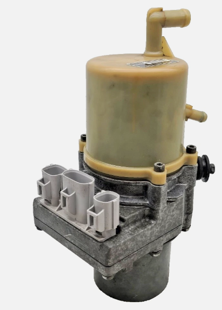
Interestingly enough, Mazda apparently has been using electrically-driven power steering pumps in their gas-burning cars for a while. The DIY EV conversion community has latched onto these as natural drop-in replacements and a good amount of community-written documentation has sprung up about these pumps, which is terrific for me. I'll share more about this in a later entry, I promise.
Unfortunately, I don't really have an exact part number to share here, but if you go on Ebay and just search around for "2004-2009 Mazda 3 Electric Power Steering Pump", you'll get a lot of results that are mostly in the right ballpark. They should look like this:
Vacuum Pump
For those who might not already know this, when you press the brake pedal in your car, more likely than not, the amount of force you're putting on the brake pedal is actually getting amplified by the car through a device called a brake booster. That is, it actually requires a lot of force to clamp the brake pads down in order to bring your car to a stop, and so auto manufacturers have stuck these in almost every car to make it easier for you, the driver, to stop your car.
Typically, in engine-driven cars, these boosters are powered by the engine vacuum. Engines operate by sucking in a ton of air so they can mix it with fuel and burn the resulting mixture. Because they suck in so much air, that creates a good amount of vacuum pressure, and engineers realized that vacuum could be used in various places around the car anywhere you needed to actuate something, and one of those places happens to be the brake pedal.
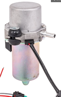
Since I don't have an engine anymore, I needed something to create that vacuum for me, so I found this pump from a supplier called JEGs that seems to sell parts to performance tuners. (If the link rots, the part number is 555-63019). It looks like this:
Coolant Pump
The Tesla battery modules, along with the inverter that I bought, require liquid cooling. To circulate all that coolant, FlashDrive Motors provided with an old-model Tesla coolant pump:
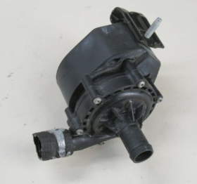
Nowadays, googling "Tesla Coolant Pump" will return all kinds of different things since Tesla has changed the design of their coolant system. If you want the exact pump that I used, you should look up "Lingenfelter L330070000".
Relay/Fuse Box
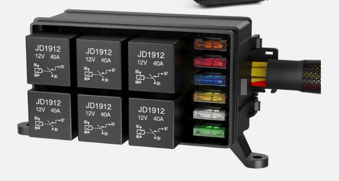
I ended up buying some random fusebox from ebay. Part number doesn't really matter. It was a 6-output fusebox, and each output was controlled by its own individual relay.
Power Wiring
Hopefully I'll be able to put together a more comprehensive schematics package, but I really need to start writing stuff down before I forget it.
Pinouts
In order to read the subsequent diagram, you'll need to know how I'm identifying the different pins on each device.
The power-steering pump has three connectors. In the mazda3 service manual, it labels them as 1, 2, 3 like so:
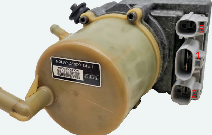
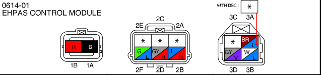
Along with the following pin numberings. The pins are numbered as if you are looking at the connectors on the pump.
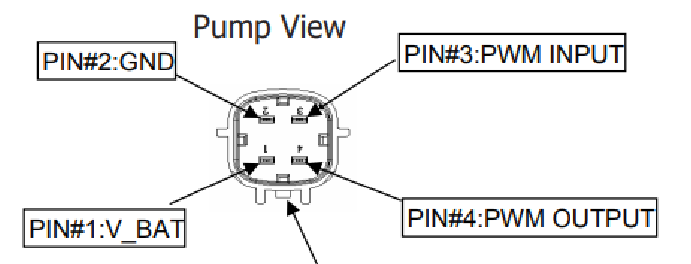
The coolant pump is pretty simple. It came with a 4-pin connector, but we only use 2. One pin is ground, and the other pin hooks up to the JIB-H9 chassis connector, pin 4, according to the JIB H9 installation manual. The JIB-H9 is responsible for activating the coolant pump and has a fused output for it. Again, the pinout view here is oriented as if you were looking at the connector on the pump.
The vacuum pump is super simple and doesn't really need a pinout diagram. The red wire goes to the fusebox, and the black wire goes to ground, simple dimple.
Wiring
Note that the image is an SVG, so you can zoom in as much as you like if you need more detail.
Note that relay 4 is modified such that the ground contact of that relay is guarded by the vacuum switch.