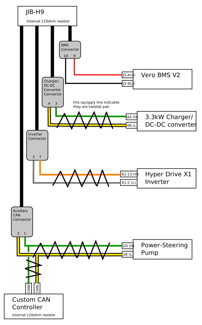
Schematics Page 2: CAN Bus
This page will be an in-depth explanation of the CAN bus that was installed on the car. I actually don't know if the Subaru Baja itself provided its own CAN bus. As far as I can tell, from poring through the wiring diagrams, I actually can't seem to find any CAN low/high wires, so it's making me wonder if this predates the advent of CAN networks in Subaru vehicles. When I looked at the wiring diagram for the instrument cluster, for example, I saw a lot of connection points for individual lights and sensors, but nothing for CAN bus wires, which is where I definitely would have expected to see something.
Parts List
JIB-H9 VCU
This part was described in some detail in the previous blog post, so I won't really get into it here. Suffice it to say that it has a 500kbps CAN controller onboard and provides termination for one end of the bus.
3.3kW Elcon/TC Charger/DC-DC Converter
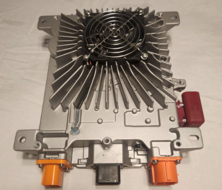
This is a part that I also bought from FlashDrive motors.
One thing to note about these converters is that the CAN bus speed is only configurable upon order from the factory. It seems that at one point, the manufacturer configured them with a default bus speed of 250kbps, but I purchased mine from FlashDrive which configures then to 500kbps, which matches the bus speed required for a lot of other components that are going to be on this CAN bus.
Power Steering Pump
This was also described in depth on the previous blog post. As mentioned previously, it appears that these are rather popular as drop-in replacements for belt/crank-driven power-steering pumps in EV conversions, and so there is a large body of documentation available for these things.
There appear to have been about three generations of these pumps. The first generation had three connectors: the beefy main power connector, a connector for feeding in raw vehicle and engine speeds, and a connector for the steering wheel angle sensor. If you have this pump, this post on DIYElectriCar is a terrific writeup for how to wire up your pump.
The second generation seems to have replaced the second connector with a connector for CAN bus wires instead. This is the one that I seem to have, and will be writing up about in-depth.
The third generation only has two connectors. It removed the connector for the steering wheel angle sensor, and seems to just rely on the CAN connector for steering wheel angle data. I suppose a lot of what I write about can actually be applicable to this version of the pump as well.
Diagrams showing the pinouts of these connectors are also available on the previous blog entry.
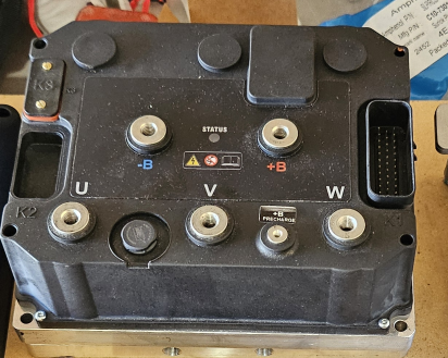
Hyper Drive X1 Inverter
This is the inverter that actually controls the motor. The model that I purchased was the one with isolated logic, configured for the 144V motor.
Vero BMS V2
The final component to mention here is the Vero BMS V2. I spent a lot of time figuring out that this thing is supposed to communicate with the Elcon/TC charger over CAN. It appears that the charger expects to receive regular messages from the BMS over CAN and if it sees those messages, it will then begin charging the battery pack if it sees that the wall plug is hooked up.
As for what message specifically it's looking for, I'm not too sure.
Custom CAN Controller
The power-steering pump has an internal controller that controls the output pressure of the pump based mainly on vehicle and engine speed. I was lucky enough to find this writeup on github explaining the messages that the pump was expecting, and the internal logic inside the controller. I'll just copy over the most relevant text here:
The protocol is fairly simple: The pump expects a message on 0x201 that contains both the engine speed and vehicle speed. The pump will not run until it receives a message indicating that the engine is above 500 rpm or so. Increasing vehicle speed will gradually reduce assist.
The late model pump recieves steering angle changes via CAN on 0x082. This message is not an absolute steering angle, rather a delta value. The early model expects steering angle changes via the steering angle sensor inputs.
The "idle" pump speed is fairly low and will yield poor P/S performance without the steering angle input. If you do not have a power steering angle input, consider using a potentiometer to dial in a "constant" level of steering change to suit.
My pump does not read steering angle input over CAN, but instead relies on a discrete steering wheel angle input. The writeup I linked above also comes with some example code here. From looking at the code, it appears that this steering wheel angle data comes as a quadrature encoder signal, so I'm going to need to figure out how to spoof that on my end, or if I can just directly connect my Subaru's steering wheel angle sensor directly to the pump.
In order to provide these values, I'm using an Arduino Nano hooked up to an MCP2515 CAN Tranceiver/Controller chip mounted on a breakout board. There are a million guides out there on how to use these things, but for record-keeping sake, this is how I wired up my boards:
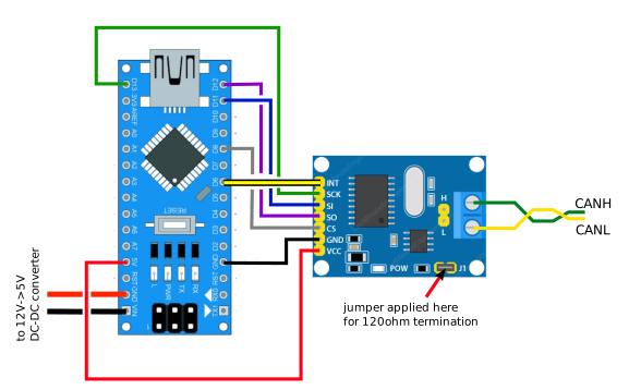
The code controlling the board can be found here
I also decided to make this the other end of the CAN bus, so it terminates on the MCP2515 breakout board with a 120ohm resistor.
Wiring Diagram