

Well, it's been like two months now since my last entry. Doesn't mean I haven't been working on it since then, but it's been hard for me to find time to write stuff in this blog. A lot of stuff has been happening with my involvement in DSA (which I feel like I ought to blog about as well since it's such a big part of my life now X-D).
The major things that have transpired since then are that I've been focusing on mounting the electric motor to where the old engine used to be. Also, sadly, I have not been able to find a buyer for the old engine yet, so it's still sitting like a sad lump on the floor of my garage.
Making the Flywheel Flange Adapter
I want to be able to still shift gears in this car, so I'm going to need to keep the old clutch + flywheel and figure out how to mount them on the new electric motor. To this end, I designed this simple hub to mount the flywheel to:
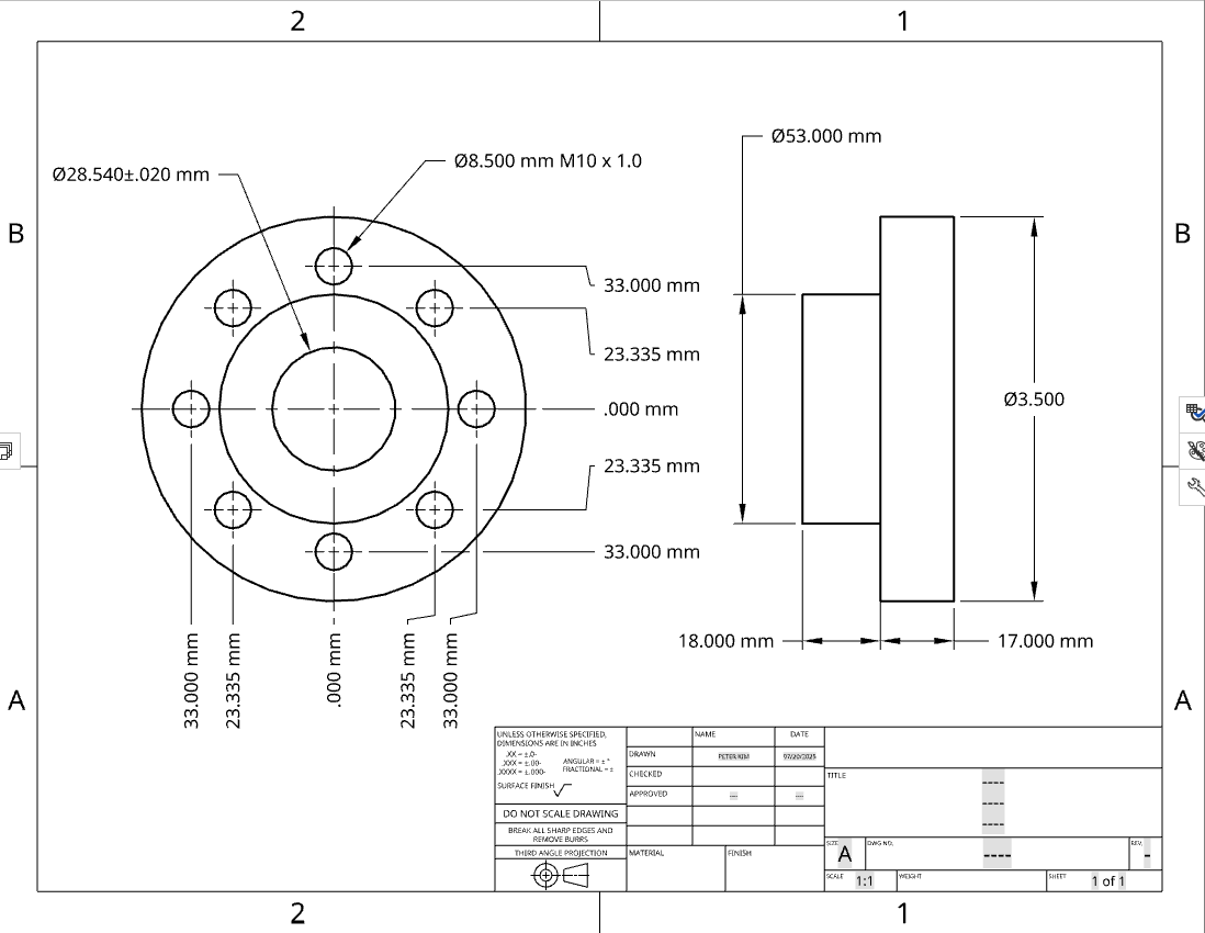
There's a 1/4" keyway that's not in the model, but that's pretty easy to conceptualize. The critical feature here, however, is the hole that the shaft will fit through. I wanted to size it just right so that it I could shrink fit the hub to the shaft. Through a bunch of esoteric calculations that I no longer remember the details of, I somehow landed on the notion that the hole for the shaft would need a nominal dimension just 0.002" smaller than the shaft, with only around 0.0006" of tolerance for that dimension.
When I first tried making this, I went about it ass-backwards. For parts like this, certain features are going to be more difficult to make than others, mostly due to the precision required. And it's usually a better idea to start with those features first, if possible. That way, if you screw it up, you won't have sunk so much time into it that you'll then have to throw away. On this part, the hole that the shaft fits into was by far the feature with the strictest tolerance, but I ended up making that last, after I'd already turned down the flang and drilled and tapped all 8 mounting holes. And of course, I fucked it up. The final hole ended up being about 0.001" or 0.002" too large, meaning I wouldn't be able to shrink fit it on the hub, and I had to basically scrap this part.
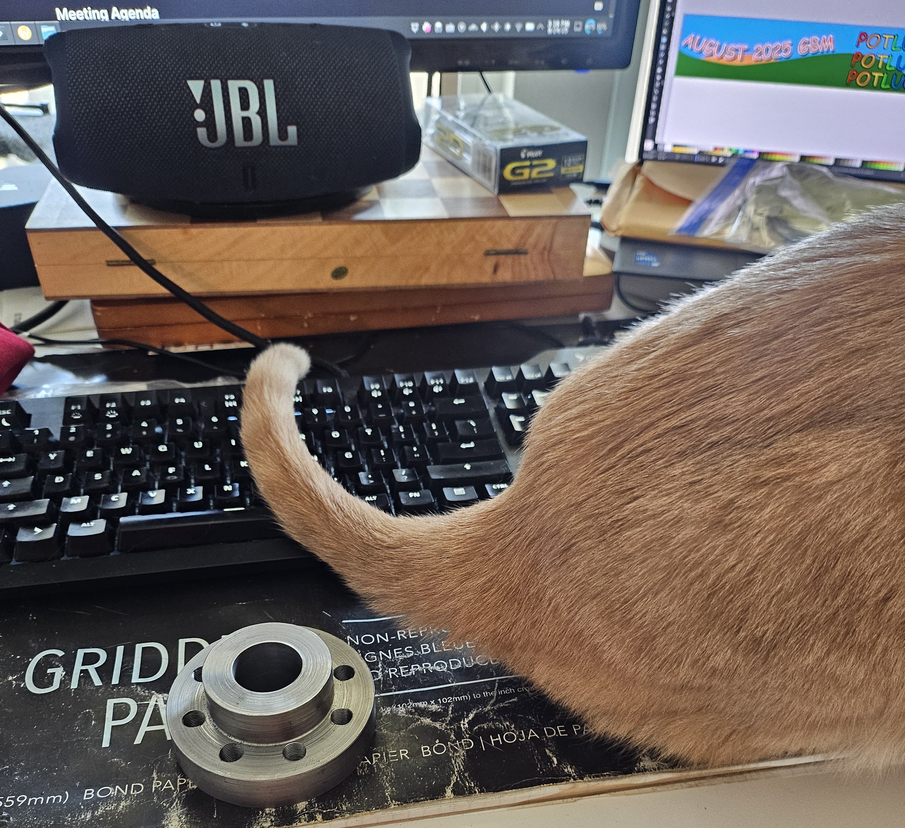
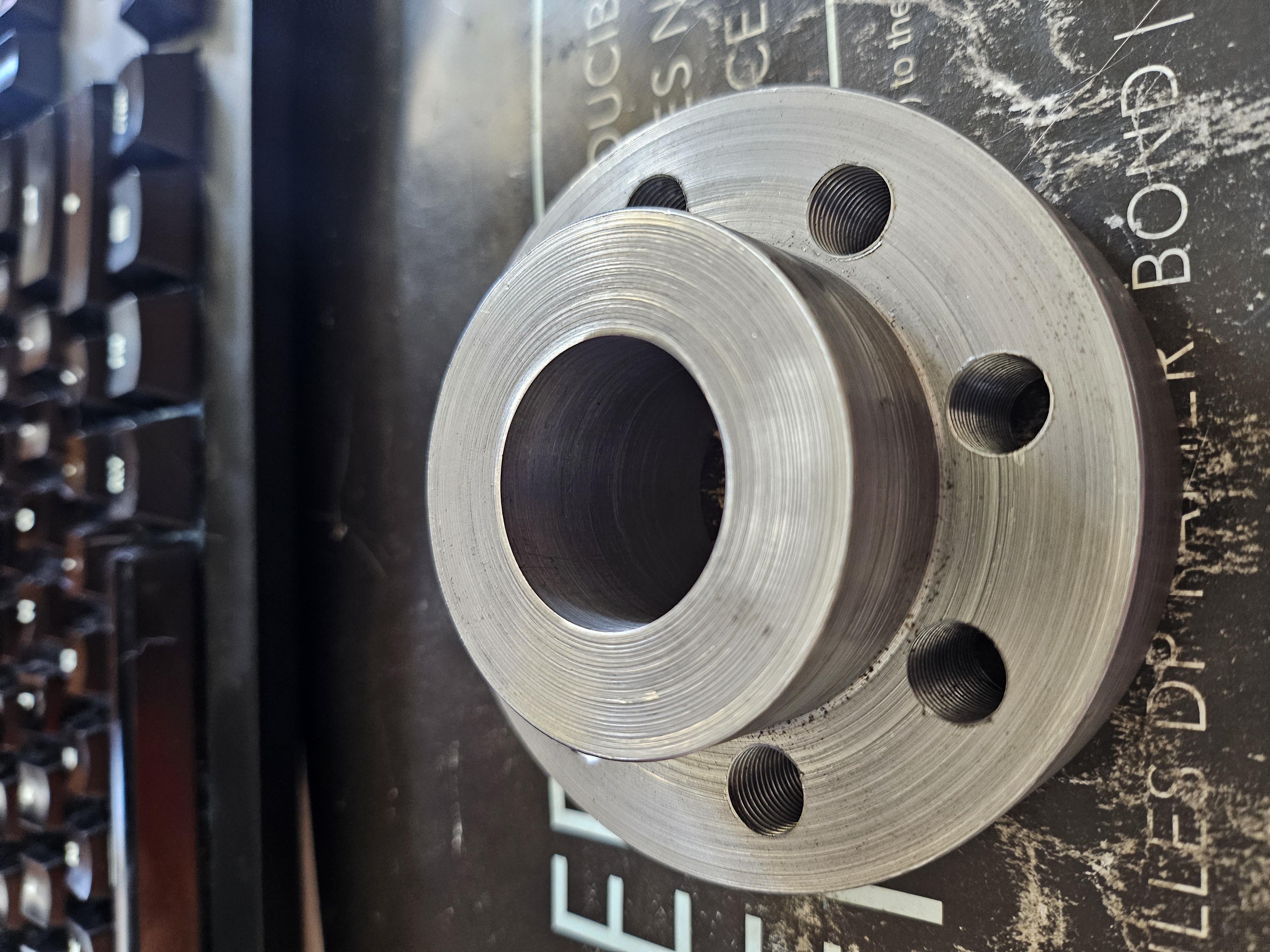
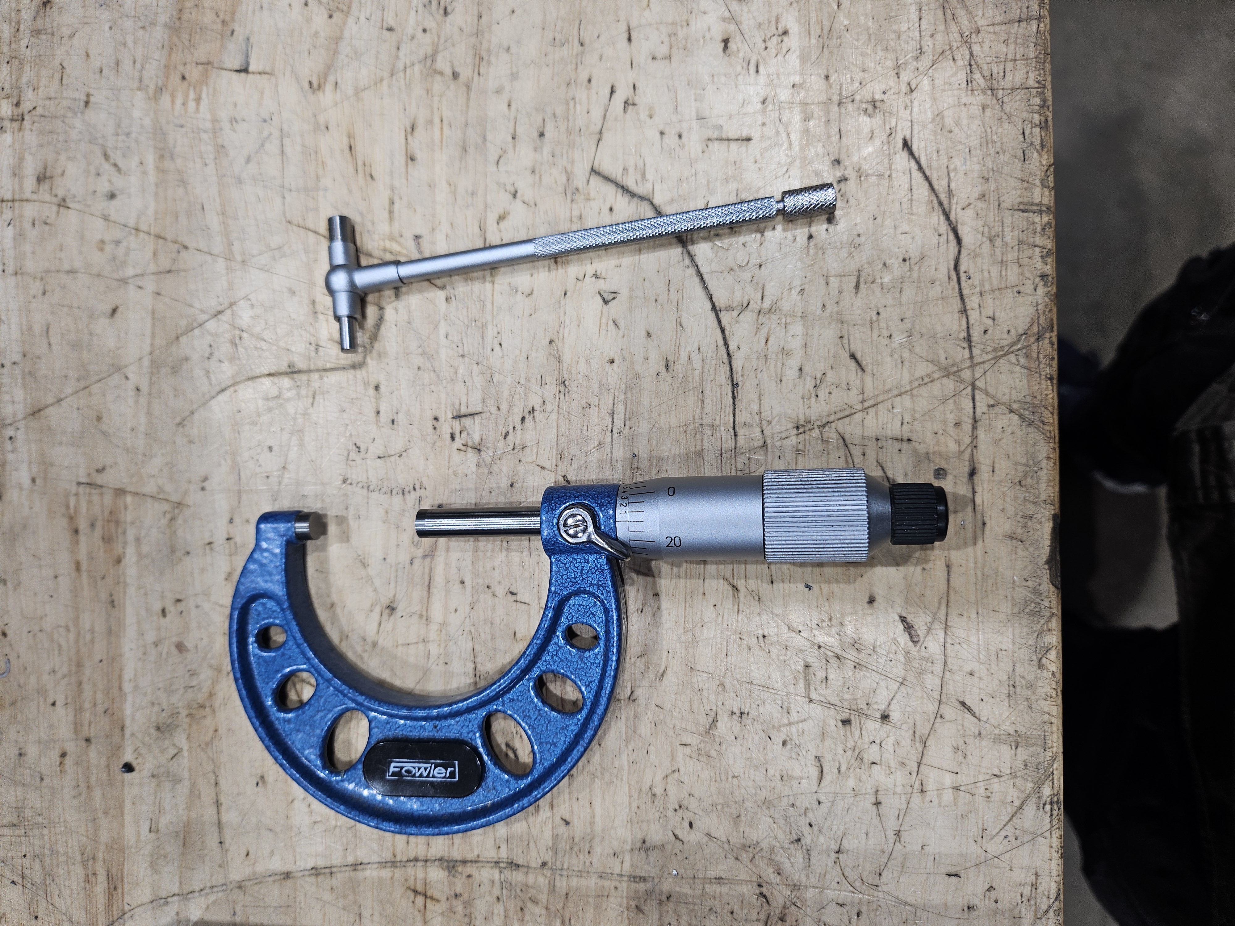
That was pretty bitter nuts, and like I usually do when I fail, I just gave up for a while and faffed around with some other stuff before finally coming back to tackle this again. This time, I tried being a little more intelligent about it. When I first tried making this, I was keeping track of the diameter of that internal hole by using the DRO on the lathe and referencing that against measurements I would take with a pair of calipers. This time, though, I discovered that the makerspace I go to, ASMBLY, had a set of internal telescoping gauges lying around and a set of micrometers, and these proved to be far better for keeping track of the actual internal diameter of the hole I was making.
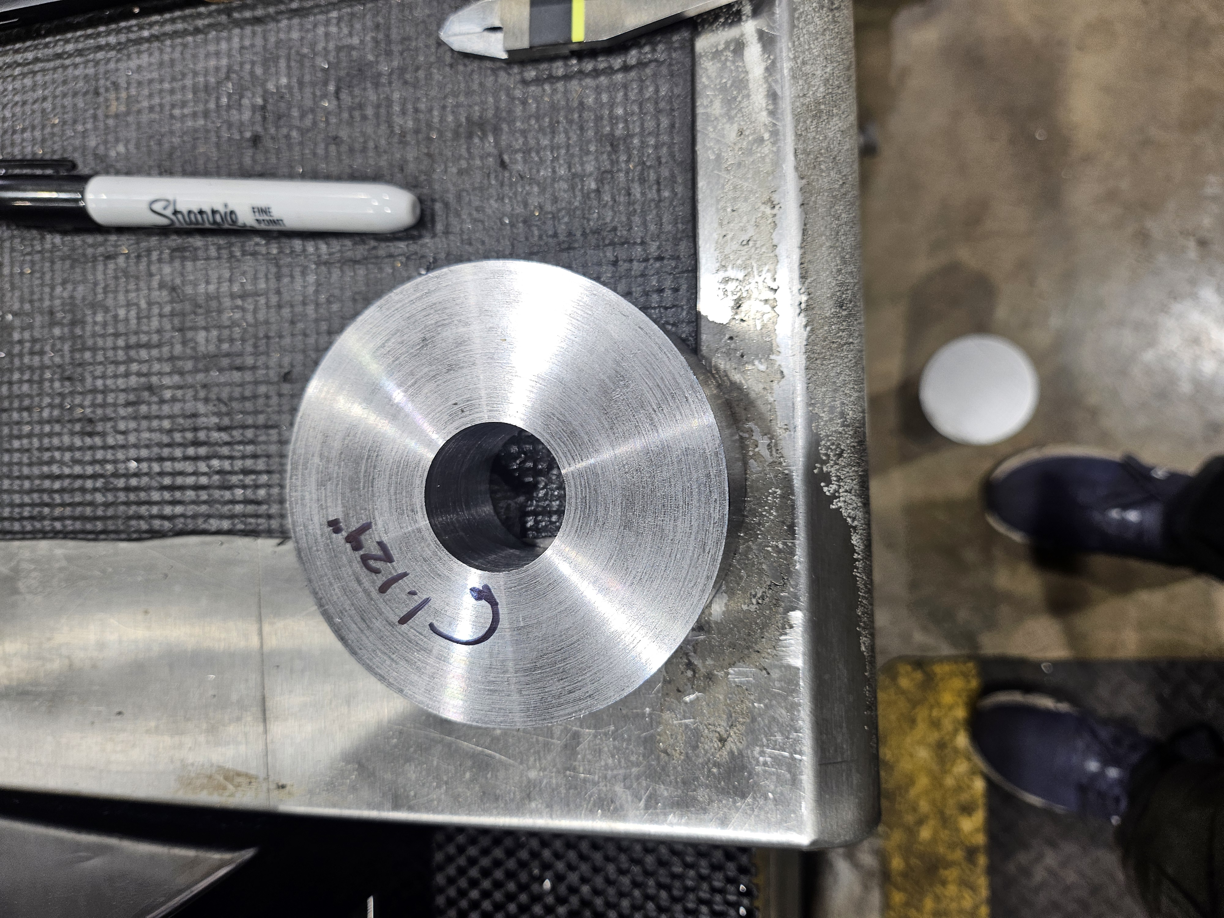
Eventually, I finished boring out the hole, and it only took me a cool 2 and a half hours to do! But honestly, it felt much better this time around, and I was quite pleased with myself at the end of it all. Even though it looks like any old hole, I was able to hit my dimension pretty well, at almost exactly 1.1240", which is about 0.0004" off from my nominal dimension and within the 0.0006" tolerance that I needed.
Mounting the Motor and The Rest of the Batteries
The other major thing I've been wasting my time on is figuring out how I'd mount the electric motor and the other three batteries. Ultimately, I ended up with this design, and I'm quite pleased with myself about this one as well:
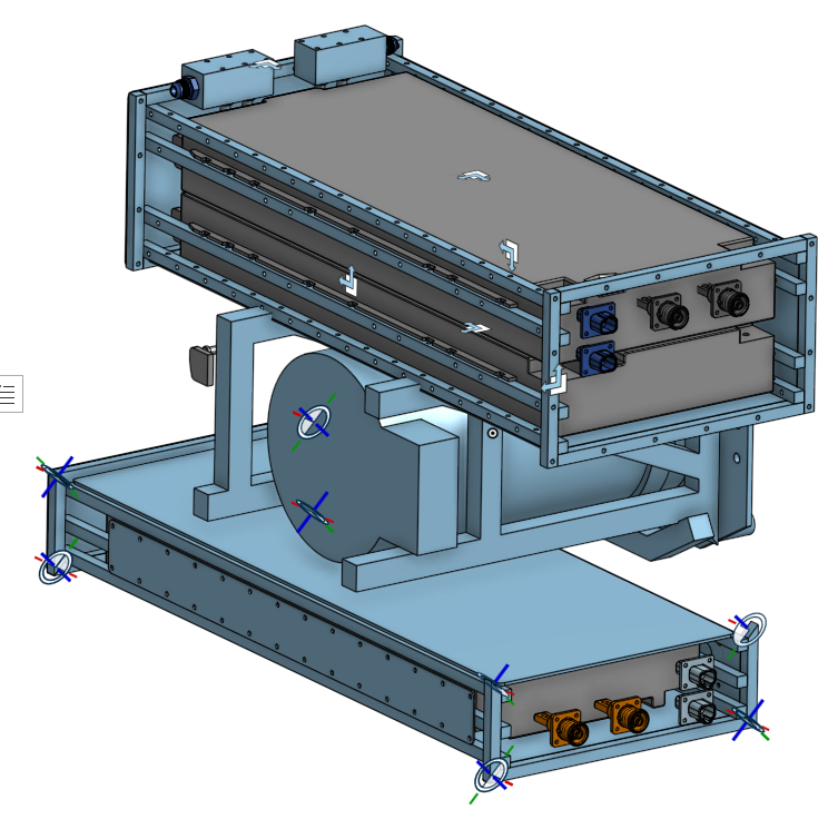
Hopefully it's easy to see what's going on here. I basically build a small "cage" around the motor that the rest of the batteries will hang off of, and this whole assembly will be bolted to the transmission. All told, this should weigh around 250 pounds, around 50 pounds lighter than the engine I pulled out of it.
I'm still in the process of fabricating this assembly, but as of now, the cage has been (mostly) fabricated:
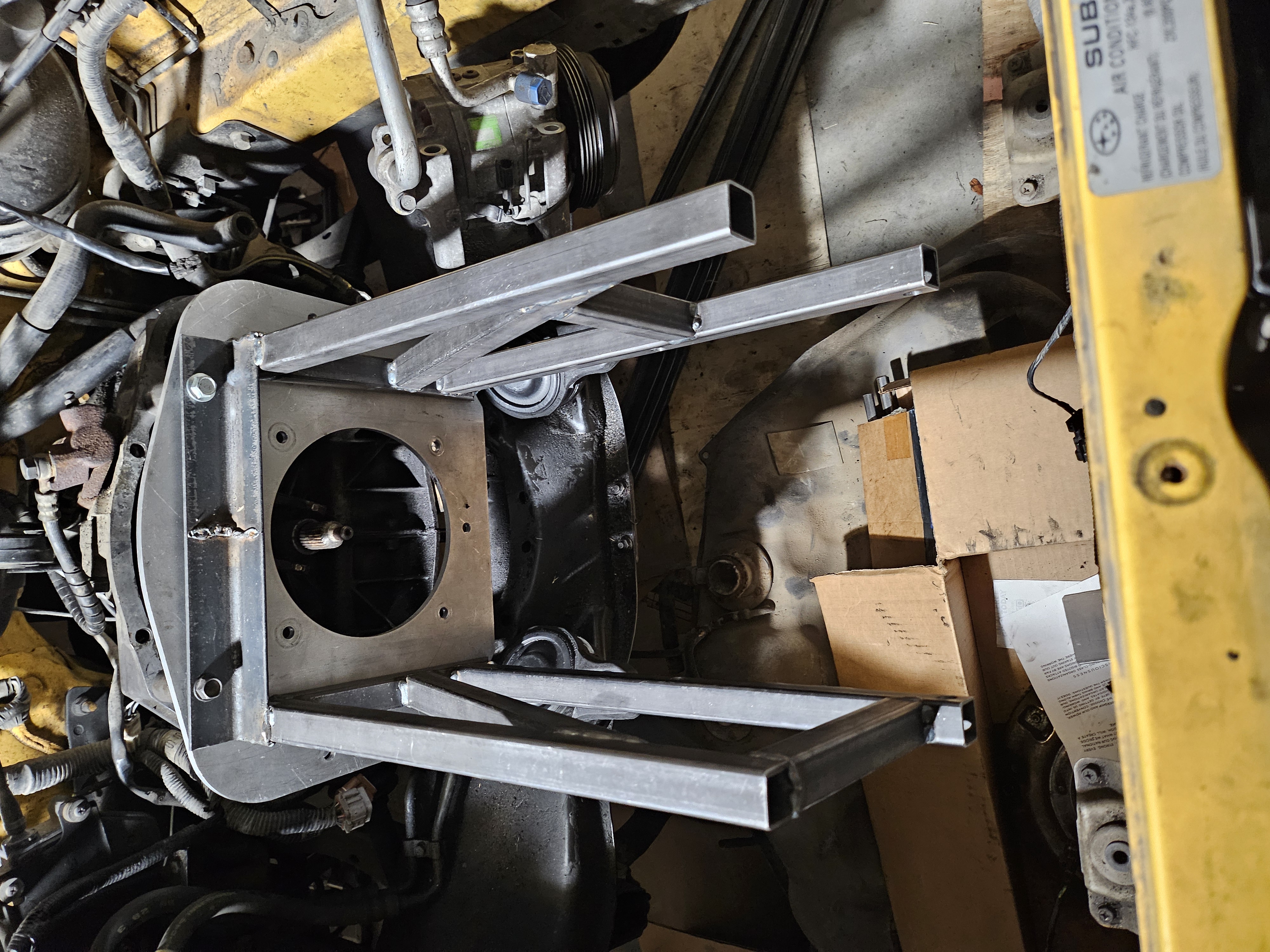
The biggest remaining question mark for me right now is how exactly I'm going to secure this cage to the motor mounts. Right now, the whole thing just kind of rests on the motor mounts. Each mount has two holes, and as far as I can tell it seems that these holes are mainly to just keep these mounts located on the engine, they are not intended to bear a lot of load themselves, because the majority of the load needs to be transmitted through the main pad (the big circle in the middle of the mount).
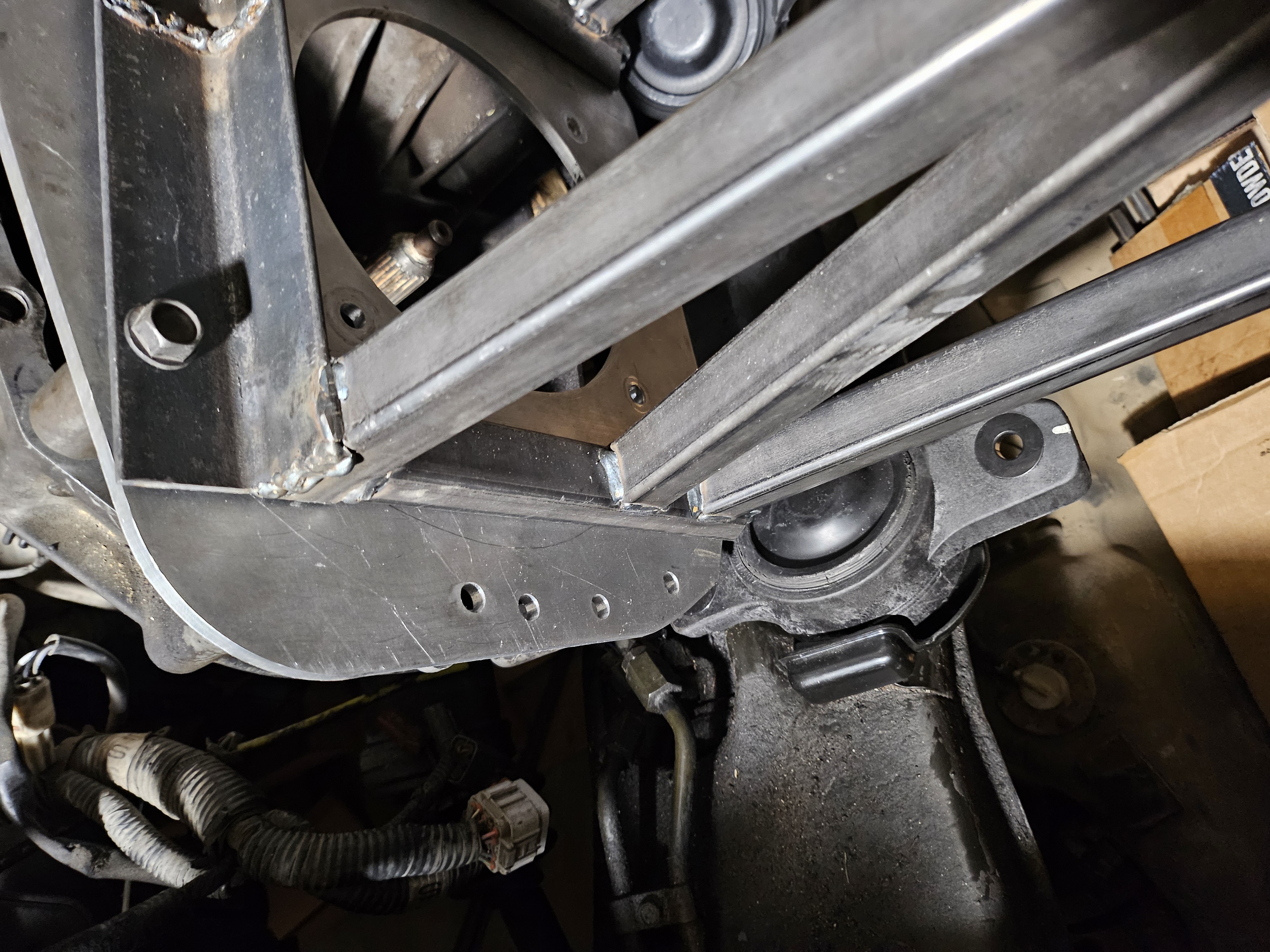
I get the feeling that I'm probably going to have to fabricate something in place that can snake around all these weird little corners and crevices. I also really need to clean off all that old dried power-steering fluid that's been dripping on that lower subframe crossmember all this time. The thing is seriously crusty.